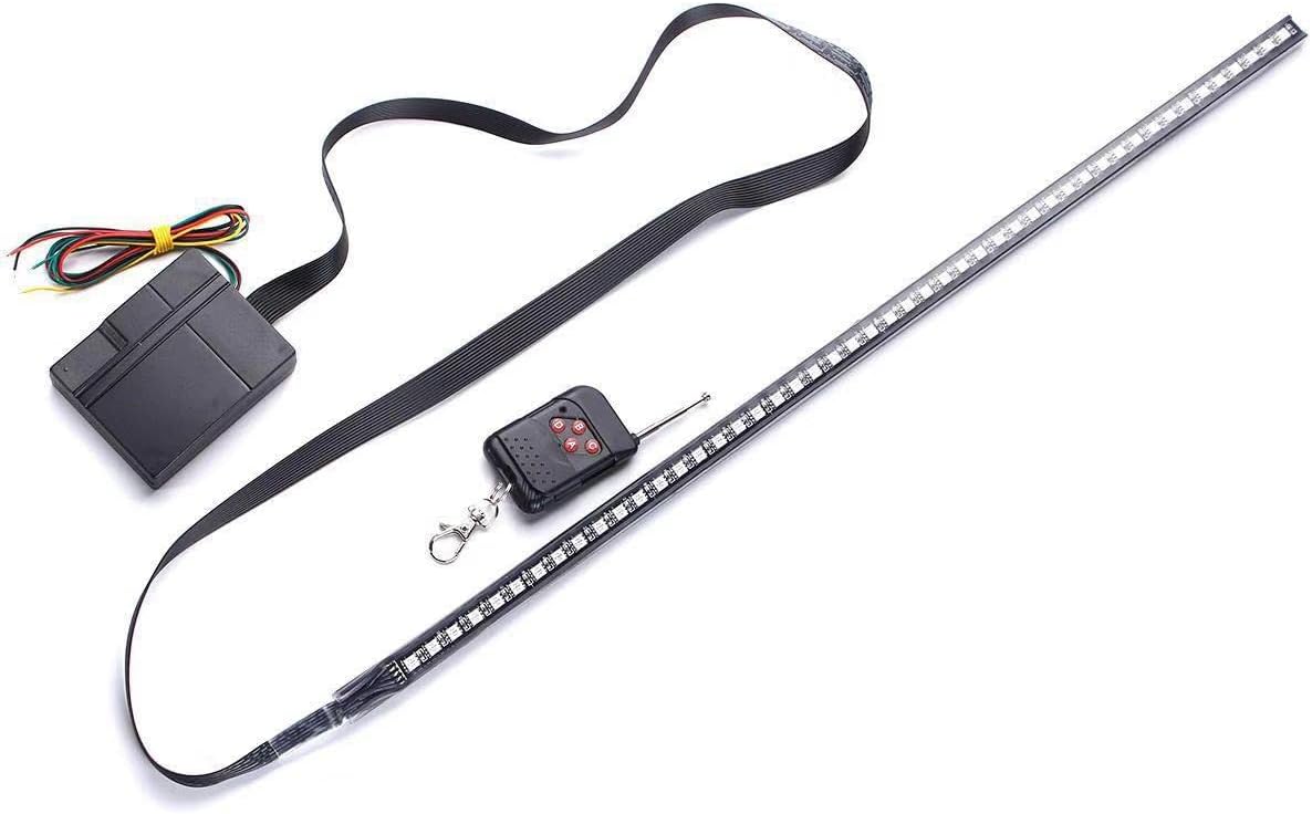
WIVION Car Strobe Lighting Strip Kit,Knight Night Rider Light Bar 7 Color 147 Modes 48 LED RGB 22'' Flashing Car Strobe Lighting Strip Kit 12V
£9.9£99Clearance
Shared by
ZTS2023
Joined in 2023
82
63
About this deal
Note: The 4017 IC must be connected plus and minus through pins 16 (+) and 8 (-) for it to work. Components Needed Nine male/female jumper wires (I used a selection of different colours which makes things easier to ID)
The number of bands (3,4,5 or 6), indicates their tolerance (more bands is generally higher precision).
You should get output on the version you are using and then a listing of all the pins with the readall command. You don’t need a keyboard or monitor for this tutorial – if your Pi is on the network you can log in via ssh and do everything from a terminal. The counter sets one of its 10 outputs high depending on where in the counting sequence it is. So if it’s at 0, output 0 will be high. If it’s at 5, output 5 will be high. And if we have an LED connected to the output, the LED will light up. This is the first part of a two parter on creating the K.I.T.T. light bar with LEDs using your Pi (I know, awesome, right?). In essence all you need to do is ask for 330 ohm resistors, but the info above will help you if you are given blue ones or brown ones and you don’t want to feel like an idiot for asking what the difference is (like I did – I knew I should have paid more attention when I was little and my Dad was fixing the telly).
Then test the 555 timer oscillator by connecting an LED in series with a resistor on the output. With the values chosen above, your LED should blink about 3 times per second. This is the list of items you’ll need. If you want clarification on any of these (buying electrical components is a bit of a leap in the dark the first time you do it), have a look at the pictures and further info below. If you’re pretty familiar with these things, then grab the list, skip the details and move onto Step 2.
More Circuits & Projects Tutorials
Note that when you CTRL-C out of the program, your LED may remain on – this will happen if you interrupt the program before the GPIO pin is told to stop the output. It will be reset when you run your code again, but you may want to avoid pulling wires in and out when the GPIO pin is active, just in case. Note that for this first step, the wiring on the Pi is the same for revision 1 and 2 boards. Step 4 – Run Your Code The LED bridges to another row, 55, and the circuit continues into our resistor, which is also plugged into row 55.
*So you can easily identify outgoing links on our site, we've marked them with an "*" symbol. Links on our site are monetised, but this never affects which deals get posted. Find more info in our FAQs and About Us page.
 Joined in 2023
  82
82  63
63
